
Gas-Hydraulic Buffer
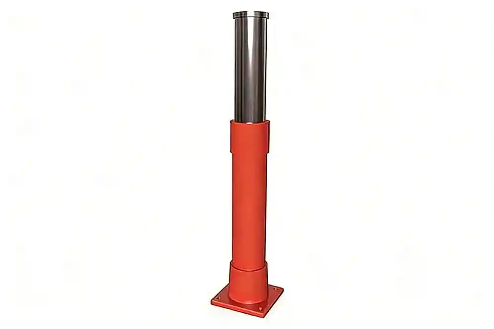
Gas-Hydraulic Buffer uses hydraulic oil for controlled energy absorption and high-pressure nitrogen gas for elastic reset. Designed for crane rail end stops, it reduces peak impact forces, protects structures and drives, and lowers maintenance costs under heavy-duty operation.
As a high-performance type of crane buffer, it is widely applied in bridge cranes, gantry cranes, and heavy industrial lifting systems where reliable end-stop protection is required. The gas-hydraulic design ensures stable deceleration even under frequent and high-energy impacts.
- Material: hydraulic oil, high pressure nitrogen, seamless steel
- Loadable speed: <3.3m/s
- Recommended service life: 5 years
- Application: Heavy crane, port machinery, mining machinery, elevator
Working Principle and Performance of Gas-Hydraulic Buffer
Working Principle
A plunger, cylinder, piston rod, piston, and internal chambers are the primary components of a gas-hydraulic buffer. The hydraulic oil in Chamber A is pressurized and sent through a throttling aperture into Chamber B when the plunger is struck and enters the cylinder. The piston is propelled by the flowing oil to compress the gas chamber.
The buffering cycle is finished when the compressed gas expands and pulls the piston back during the return stroke, forcing the hydraulic oil from Chamber B through the throttling orifice and into Chamber A.
Energy Absorption Principle
During the compression stroke, hydraulic oil passing through the throttling orifice generates viscous damping, converting most of the impact energy into heat. A smaller portion of the energy is stored as internal energy by compressing the gas in the gas chamber.
During the return stroke, the compressed gas releases its stored energy, overcoming return damping and converting part of the internal energy back into heat.
Performance Features
High impact energy absorption efficiency
Low reaction force during buffering
Stable and controlled deceleration
Long service life under heavy-duty operation
Main Models of Gas-Hydraulic Buffers
Type 21 Hydraulic-Pneumatic Buffer Drawing
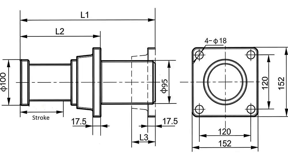
Type 21 Hydraulic-Pneumatic Buffer - Outline & Installation Dimensions
| Stroke (mm) | Energy Absorption (KJ) | Maximum Reaction Force (KN) | Dimensions (mm) | ||
| L1 | L2 | L3 | |||
| 50 | 10 | 245 | 260 | 134 | 75 |
| 100 | 21 | 245 | 420 | 184 | 75 |
| 150 | 31 | 245 | 584 | 234 | 75 |
| 200 | 42 | 245 | 700 | 360 | 118 |
Type 21 Gas-Hydraulic Buffer - Core Rod Model
| Stroke (mm) | Impact Weight | |||||||
| ≤1.7t | ≤3.5t | ≤7t | ≤13t | ≤25t | ≤50t | ≤100t | ≤200t | |
| 50 | 51 | 52 | 53 | 54 | 55 | 56 | 57 | – |
| 100 | 101 | 102 | 103 | 104 | 105 | 106 | 107 | 108 |
| 150 | 151 | 152 | 153 | 154 | 155 | 156 | 157 | 158 |
| 200 | 201 | 202 | 203 | 204 | 205 | 206 | 207 | 208 |
Type 21 Hydropneumatic Buffer - Model Identification
| Weight | Model Identification | |||||||
| Stroke (mm) | Pattern | 21-N-FS-100-102 | ||||||
| NFS | NBS | NCP | Model | Sealing Type | Mounting Type | Buffer Head | Core Rod No. | |
| 50 | 10.6 | 10.6 | 7.9 | 21 | N-Normal Temperature Seal H-High Temperature Seal | FS-Front Mounting Base BS-Back Mounting Base CP-No Base Mounting | φ100-Head Diameter | See Table Above |
| 100 | 13.8 | 14.1 | 11 | |||||
| 150 | 17.1 | 17.1 | 14.4 | |||||
| 200 | 19.2 | 21.5 | 16.3 | |||||
Type 4 Hydraulic-Pneumatic Buffer Drawing
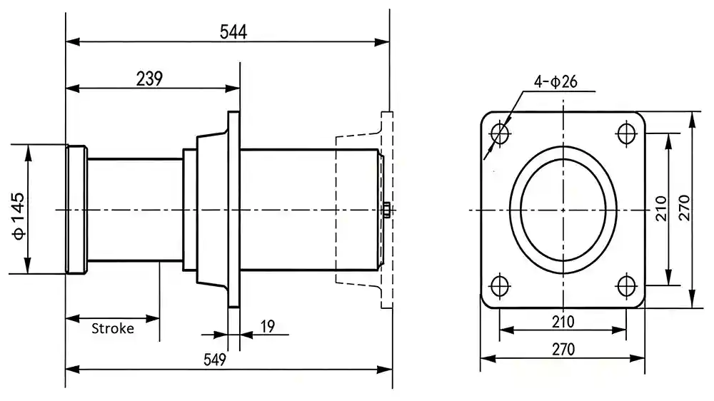
Type 4 Gas-Hydraulic Buffer - Basic Performance Parameters
| Stroke (mm) | Energy Absorption (KJ) | Maximum Reaction Force (KN) |
| 114 | 84.25 | 980 |
Type 4 Hydropneumatic Buffer - Core Rod Model
| Impact Weight | ≤5t | ≤10t | ≤20t | ≤40t | ≤80t | ≤125t |
| Core Rod No. | 2 | 4 | 5 | 7 | 8 | 10 |
Type 4 Hydraulic-Pneumatic Buffer - Model Identification
| Model | Weight | Model Identification | ||||
| 4-N-FZ-145-02 | ||||||
| Model | Sealing Type | Mounting Type | Buffer Head | Core Rod No. | ||
| NFZ-145 | 50 | 4 | N-Normal Temperature Seal H-High Temperature Seal | FZ-Front Mounting Base BZ-Rear Mounting Base CF-No Mounting Base | φ145-Head Diameter φ330-Head Diameter | See Table Above |
| NFZ-330 | 66 | |||||
| NFZ-145 | 64 | |||||
| NFZ-330 | 80 | |||||
| NFZ-145 | 38 | |||||
| NFZ-330 | 54 | |||||
Type 50 Hydraulic-Pneumatic Buffer Drawing

Type 50 Hydropneumatic Buffer - Outline & Installation Dimensions
| Model | Stroke (mm) | Energy Absorption (KJ) | Maximum Reaction Force (KN) | Dimensions (mm) | |||
| L1 | L2 | L3 | D | ||||
| 52 | 250 | 106 | 500 | 871 | 527 | 875 | φ140/180 |
| 53 | 300 | 127 | 500 | 1006 | 577 | 1010 | φ140/180 |
| 54 | 400 | 170 | 500 | 1277 | 677 | 1281 | φ140/180 |
Type 50 Gas-Hydraulic Buffer - Core Rod Model
| Model | Impact Weight | ||||||
| ≤4t | ≤7.5t | ≤10t | ≤20t | ≤40t | ≤80t | ≤150t | |
| 52 | 202 | 203 | 204 | 205 | 207 | 208 | 210 |
| 53 | 302 | 303 | 304 | 305 | 307 | 308 | 310 |
| 54 | 402 | 403 | 404 | 405 | 407 | 408 | 410 |
Type 50 Gas-Hydraulic Buffer - Model Identification
| Weight | Model Identification | ||||||
| Model | Pattern | 52-N-FZ-140-202 | |||||
| -NFZ-140- | -NFZ-180- | Model | Sealing Type | Mounting Type | Buffer Head | Core Rod No. | |
| 52 | 55 | 59 | 50 | N-Normal Temperature Seal H-High Temperature Seal | FZ-Front Mounting Base BZ-Rear Mounting Base | φ140-Head Diameter φ180-Head Diameter | See Table Above |
| 53 | 59 | 63 | |||||
| 54 | 68 | 72 | |||||
Need a Reliable Gas-Hydraulic Buffer Solution?
Tell us your application parameters, impact energy, and installation conditions. Our engineers will help you select or customize the right crane buffer for your system.