TGL34968 wheel sets
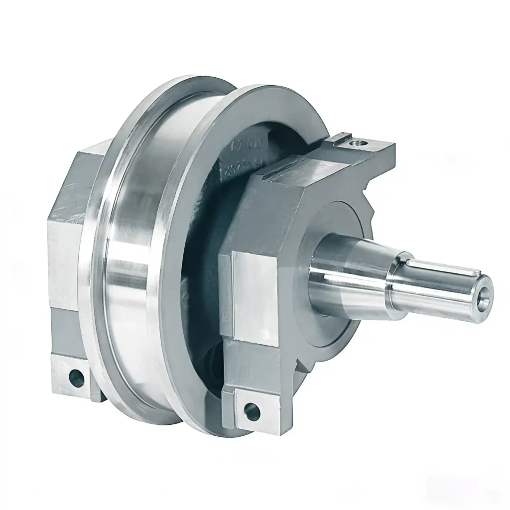
TGL34968 wheel sets are complete wheel assemblies designed for crane travel systems, compatible with driven and non-driven positions and integrated with crane wheels.
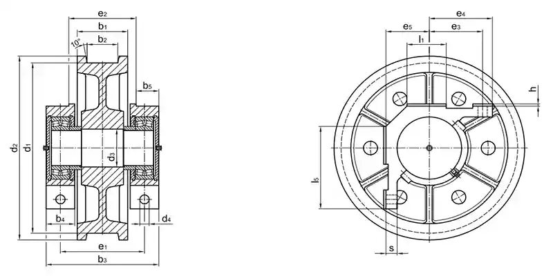
Form A1 Crane wheel with idle shaft (nondriven wheel set)
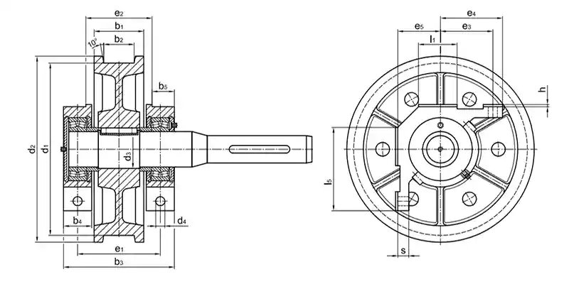
Form A3 Crane wheel with drive shaft (driven wheel set)
Designation of a crane wheel form A1 (nondriven wheel set)
with corner support, nominal - Ø d1 = 400 mm, gauge b2 = 80
mm, incl. self aligning roller bearings 222 20:
Crane wheel A1 – 400 × 80 TGL 34968
Designation of a crane wheel form B3 (driven wheel set) without corner support, nominal - Ø d1 = 400 mm, gauge b2 = 100
mm, shaft - Ø d5 = 70 mm, Wellenmaß e6 = 635 mm, incl. self
aligning roller bearings 22220:
Crane wheel B3 – 400 × 100 – 70 × 635 TGL 34968
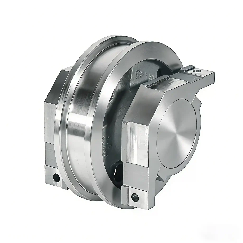
Form A crane wheels with corner support
B crane wheels without corner support and
covers
A1, B1 nondriven wheel set with idle shaft
A2, B2 driven wheel set with drive shaft for coupling
A3, B3 driven wheel set with drive shaft for hollow shaft gear unit
A4, B4 driven wheel set with drive shaft for coupling
and hollow shaft gear unit
Form A4, B4 driven wheel set with drive shaft for coupling
and hollow shaft gear unit
Form A5, B5 driven wheel set with drive shaft for hollow
shaft gear unit
The anti friction bearings are lubricated. Re-lubrication by
using the lubrication nipple in the corner support or in the outer
covers.
Material:
Wheel body GE420 (GS -70) or G42CrMo4+QT
(GS - 42CrMo4-V)
drive shaft 42CrMo4QT
idle shaft C45
corner support S355J2 G3 (St 52-3)
Wheel sets with corner support TGL 34968
(driven and nondriven)
Other material and dimensions on request.
Type with shaft ends suitable for hollow shaft drive units of
all manufacturers on request.
Order Now
Request a quotation for TGL34968 wheel sets based on your driven or non-driven configuration, wheel diameter, tread width, and bearing requirements.
Our engineers support selection with or without corner support and shaft designs suitable for coupling or hollow shaft drive units.
TGL34968 WHEEL SETS WITH CORNER SUPPORT
Crane Wheel Assembly Drawing
Crane Wheel Assembly Specification
| nominal-Ø d1 (h9) | form | b2 | b1 | b3 | b4 | b5 | d2 | d3 (m6) | d4 | e1 | e2 | e3 (tolerance) | e4 | e5 (-0,15) | h | l1 | l5 | s | bearings |
| 320 | all | 40-70 | 100 | Dimensions on request | |||||||||||||||
| 320 | all | 80-90 | 130 | ||||||||||||||||
| 400 | all | 50-80 | 120 | ||||||||||||||||
| 400 | all | 90-120 | 160 | ||||||||||||||||
| 500 | all | 50-80 | 120 | ||||||||||||||||
| 500 | all | 90-120 | 160 | ||||||||||||||||
| 630 | all | 60-90 | 140 | ||||||||||||||||
| 630 | all | 100-130 | 180 | ||||||||||||||||
| 710 | all | 60-80 | 140 | ||||||||||||||||
| 710 | all | 90-130 | 180 | ||||||||||||||||
| 800 | all | 80-90 | 160 | ||||||||||||||||
| 800 | all | 100-130 | 200 | ||||||||||||||||
| 900 | all | 90-110 | 190 | ||||||||||||||||
| 900 | all | 120-150 | 210 | ||||||||||||||||
🔧 Driven vs Non-Driven Wheel Sets – Selection Guide
| Wheel Set Type | Purpose | Key Applications | Notes |
| Driven (with drive shaft) | Provides traction and torque | End trucks, bogies, high-load travel | Ensures precise speed control and stable motion |
| Non-Driven (idler) | Supports load and alignment | Auxiliary wheels, load-balancing wheels | Reduces drivetrain complexity and maintenance |
| Typical Layout | Combination of driven and idler wheels | Most crane travel systems | Balanced load distribution and efficient crane motion |
Proper selection improves crane travel efficiency and reduces wear on gearboxes and couplings.
🔧 With vs Without Corner Support – Why It Matters
Load transmission: corner support helps transfer forces evenly from the wheel to the crane structure.
Bearing alignment & service life: ensures self-aligning roller bearings remain properly seated, reducing wear.
Maintenance & re-lubrication: provides easy access to grease nipples for bearings, simplifying upkeep and minimizing downtime.