
45° Split Bearing Box Wheel Assembly
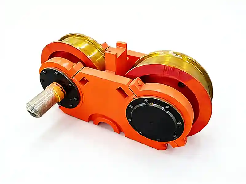
The 45° split bearing box wheel assembly is designed for heavy-duty lifting equipment where convenient maintenance and disassembly are essential.
With a split housing structure at a 45° angle, this design allows easier access to internal components, making it suitable for applications with high wheel loads and frequent servicing requirements.
- Double flange wheel design
- 45° split bearing housing
- Suitable for high wheel load conditions
- Equipped with self-aligning bearings
- Designed for heavy-duty crane travel mechanisms
How Are 45° Split Bearing Box Crane Wheel Assemblies Designed and Used?
45° Split Bearing Box Wheel Assembly Drawing
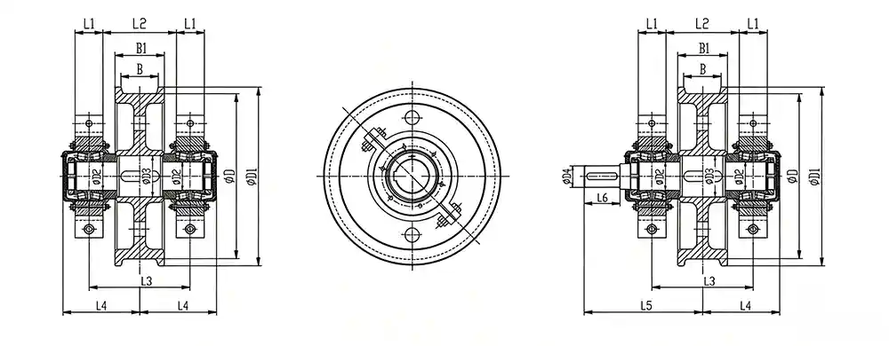
45° Split Bearing Box Wheel Assembly Specifications
| Item | D | D1 | D2 | D3 | D4 | B | B1 | L1 | L2 | L3 | L4 | L5 | L6 | Weight |
|---|---|---|---|---|---|---|---|---|---|---|---|---|---|---|
| Active crane wheels ø500 | 500 | 540 | 100 | 105 | 75 | 80~130 | 130~180 | 100 | 180 | 280 | 230 | 400 | 105 | 276~298 |
| Passive crane wheels ø500 | 500 | 540 | 100 | 105 | / | 80~130 | 130~180 | 100 | 180 | 280 | 230 | / | / | 269~291 |
| Active crane wheels ø600 | 600 | 640 | 100 | 105 | 85 | 80~150 | 130~210 | 100 | 180 | 280 | 230 | 415 | 130 | 321~386 |
| Passive crane wheels ø600 | 600 | 640 | 100 | 105 | / | 80~150 | 130~210 | 100 | 180 | 280 | 230 | / | / | 311~386 |
| Active crane wheels ø700 | 700 | 750 | 120 | 125 | 90 | 100~150 | 150~200 | 120 | 195 | 315 | 260 | 455 | 130 | 507~547 |
| Passive crane wheelsø700 | 700 | 750 | 120 | 125 | / | 100~150 | 150~200 | 120 | 195 | 315 | 260 | / | / | 494~539 |
| Active crane wheel ø800 | 800 | 850 | 150 | 155 | 95 | 100~150 | 150~210 | 140 | 225 | 365 | 300 | 500 | 130 | 747~828 |
| Passive crane wheels ø800 | 800 | 850 | 150 | 155 | / | 100~150 | 150~210 | 140 | 225 | 365 | 300 | / | / | 734~815 |
Structure and Components
The 45° split bearing box crane wheel assembly consists of four main parts:
- Wheel axle
- Crane wheel
- 45° split bearing housing
- Bearings
The split housing design allows the bearing box to be opened and serviced without removing the entire wheel assembly.
Materials and Manufacturing
- Cast steel: ZG55, ZG50SiMn, ZG42CrMo
- Forged steel: 60, 42CrMo, 65Mn
Material selection depends on load conditions and service requirements.
When to Use 45° Split Bearing Box Wheel Assemblies
This type of wheel assembly is typically used in crane systems operating under high load and requiring efficient maintenance access.
- Large lifting equipment with high wheel pressure
- Crane systems requiring frequent maintenance
- Heavy-duty travel mechanisms
- Applications where downtime must be minimized
Engineering Design Highlights
- The wheel is typically mounted at the end of the end beam web plate, reducing stress on installation bolts and improving structural reliability.
- The web plate is welded to a support ring, which provides better resistance to vibration and heavy loads compared to traditional side-mounted bolt connections.
- Due to limitations in alignment precision, self-aligning bearings are used to compensate for deviations during operation.
Get the Right Wheel Assembly
Share your load conditions, crane type, and maintenance requirements — we will help you select a suitable wheel assembly solution.